RE-TURN In Few Words


Words taken from RE-TURN RTCWEB draft

  • TURN [RFC 5766] is a protocol used to provide connectivity between users behind NAT or to obscure the identity of the participants by concealing their IP addresses.
  • The TURN server typically sits in the public internet.
  • The problem is direct UDP transmissions are not permitted between clients on the internal networks and external IP addresses in many enterprises. It is not ideal to use TURN-TCP or TURN-TLS for media because of latency.
  • In the current WebRTC implementations, TURN can only be used on a single-hop basis.
    • Using only the enterprise’s TURN server reveals the user information. Less security here.
    • Using only the application’s TURN server may be blocked by the network administrator  or may require using TURN-TCP or TURN-TLS. Less connectivity here.
  • For security and connectivity,  Recursively Encapsulated TURN (Re-TURN) is introduced. Multiple TURN servers are used to route the traffic.
  • The browser allocates a port on the border TURN server (TURN proxy) and runs STUN and TURN over this allocations. So the TURN is recursively encapsulated.
  • Only the browser needs to implement the Re-TURN and not the TURN proxy or the Application TURN server.

Reference

draft-ietf-rtcweb-return-02

OpenWRT As a Virtual Router

Introduction

OpenWRT is GNU/Linux distribution for embedded devices. You can run OpenWRT on a dedicated hardware or you can have OpenWRT as virtual router which can be somewhere on cloud.

When we talk about the cloud image, we care about the size of the image which plays very important role in the space that the VM will occupy on disk and in the memory in addition to the time needed to spin a new virtual machine. Time to spin a virtual machine becomes more critical when you create a virtual machine depending on your consumption of your resources where you need to delete a virtual machine when it is not needed (e.g. low load) or when you need to create a new virtual machine quickly when you reach a threshold where you have high load and still you need to keep your service available.

In this article i will show you how simple is the creation of a small Linux image (OpenWRT) for cloud.

Clone the OpenWRT Repo from GitHub

  • Install the source:
    • # git clone git://git.openwrt.org/openwrt.git; cd openwrt
  • Open the file: feeds.conf.default  and comment the packages that you don’t want to be installed. For example if you have your own telephony then comment the telephony.git which includes installing Kamailio, OpenSIPS, Asterisk,….etc.
  • For cloud, we need the cloud-init for the early initialization of the virtual machine/instance (e.g. enable the SSH remote access). I am going to use another cloud-init which is rc.cloud and it is a set of shell scripts that implements part of the cloud-init. The aim is making the image small. The installation of rc.cloud will be as a custom feed:

Configuration & Compilation

# make menuconfig

Now we take an example so i will configure the target system as x86 and the subtarget as KVM guest so this image can work with Openstack cloud but not Amazon (xen based).

screenshot-from-2017-01-12-11-07-18

Then we configure the target image:

screenshot-from-2017-01-12-11-07-34

For example you can select ext4 file system, change the root file system partition size, root device name (for example /dev/vda2 for kvm). Check other options that you might be interested in.

Now you need to build so you type: # make V=99

After this and according to the above configuration we will have our compressed image in “bin/x86/openwrt-x86-kvm_guest-combined-ext4.img.gz”.

Image Configuration

  • Uncompress the compressed raw image file:
    • gzip -dc  bin/x86/openwrt-x86-kvm_guest-combined-ext4.img.gz   >  openwrt-x86-kvm_guest-combined-ext4.img
  • Mount the partions within the image file:
    • # sudo  kpartx  -av openwrt-x86-kvm_guest-combined-ext4.img
      [sudo] password for binan:
      add map loop0p1 (253:3): 0 8192 linear /dev/loop0 512
      add map loop0p2 (253:4): 0 241664 linear /dev/loop0 9216
  • Mount the image file as a block device (loop device):
    • # mkdir imgroot
    • # sudo mount -o  loop   /dev/mapper/loop0p2  imgroot

If using “kpartx” and then “mount” did not work then go further below and try that     “Mounting Your Image File as a  Loop Back Device”.

  • Copy the /bin/bash to imgroot/bin:
    • # sudo mkdir imgroot/bin
    • # sudo cp /bin/bash    imgroot/bin/
  • Change  the root directory for the current running process:
    • # sudo chroot imgroot

Now if you got this error message “chroot: failed to run command ‘/bin/bash’: No such file or directory” this means the /bin/bash or its dependencies are not exist in the new root so do these to fix this missing:

  • Check the /bin/bash dependencies in the old root:
    • $ ldd /bin/bash
      linux-vdso.so.1 (0x00007ffe69bee000)
      libtinfo.so.5 => /lib64/libtinfo.so.5 (0x00007fbc74ceb000)
      libdl.so.2 => /lib64/libdl.so.2 (0x00007fbc74ae7000)
      libc.so.6 => /lib64/libc.so.6 (0x00007fbc74725000)
      /lib64/ld-linux-x86-64.so.2 (0x000055be47e4b000)
    • Move the lib/* to lib64: # sudo mv imgroot/lib  imgroot/lib64
    • Copy the files from the old root to the new root:
      • One of the above (we must copy all above): # sudo  cp  /lib64/libc.so.6  imgroot/lib64
    • Ow we try again: # sudo chroot imgroot
      bash-4.3#     —–> success

Here is our tree:

bash-4.3#ls
bin         etc         lib64       mnt         proc        root        sys         usr         www
dev         lib         lost+found  overlay     rom         sbin        tmp         var
bash-4.3#

Now we can do our changes to the image files.

On cloud (openstack or amazon), you can define security groups to protect your virtual machines from the outside. So we should keep this in mind.

In addition to this the dropbear (the SSH compatible client and server) will not allow ssh without root password so we must set the root password (/etc/shadow):

You can open the file and edit the root password or using other Linux command like ‘sed’ to set/replace the password.

Then exist from chroot and umount the imgroot folder.

Mounting Your Image File as a Loop Back Device

Do the following:

# sudo fdisk -l  openwrt-x86-kvm_guest-combined-ext4.img
Disk openwrt-x86-kvm_guest-combined-ext4.img: 122.5 MiB, 128450560 bytes, 250880 sectors
Units: sectors of 1 * 512 = 512 bytes
Sector size (logical/physical): 512 bytes / 512 bytes
I/O size (minimum/optimal): 512 bytes / 512 bytes
Disklabel type: dos
Disk identifier: 0x4ff362b1

Device                                                                         Boot Start    End Sectors  Size Id Type
openwrt-x86-kvm_guest-combined-ext4.img1 *      512   8703    8192    4M 83 Linux
openwrt-x86-kvm_guest-combined-ext4.img2       9216 250879  241664  118M 83 Linux

Then the offset will be 512 * 512 = 262144
Then we can mount the image:

the boot: [binan@dhcppc0 xen]$ sudo mount -o loop,rw,offset=262144 openwrt-x86-kvm_guest-combined-ext4.img  imgroot/

the rest: [binan@dhcppc0 xen]$ sudo mount -o loop,rw,offset=4718592 openwrt-x86-kvm_guest-combined-ext4.img  imgroot/

Now you can change the root.
chroot: $ sudo chroot imgroot/


Push Notification For WebRTC Mobile Applications

Introduction

wake-up-callThe mobile push notification is a way to send a message to mobile devices via their services (e.g. Google, Apple, Kindle,…). The message reaches the operating system first through a shared channel between all applications running on the same device.  Then it is forwarded to the target application listener and then the application can react upon this. The application needs to understand the format of the push message.  The mobile needs to be connected to its service (e.g. Google GCM for Android devices, APN for Apple devices, ADM for Kindle devices) so it can receive the push messages on the shared channel. Any successfully authenticated third party server can send the push messages to its applications on the devices via the corresponding service which sends the messages directly to the devices. So the third party server needs to know the type of devices if it wants to support multiple types of devices.

The Google Cloud Messaging (GCM) is the Google mobile free push service for sending data or notification to android devices. Apple Push Notification (APN) is the Apple mobile push service (not free) for sending notifications or data to Apple devices.  In addition to the original push notification, APN supports what is called VOIP push notification where the push notification message has priority over other push notifications so it can reach the device in real time. GCM also supports the priority as a field in the message itself and not as a type of service offered to the customer as APN. So if the GCM push message has high priority, it will reach the device quickly but it costs the device more power. Whereas if it has normal priority, it could not reach the device in real time but this costs less power consumption. In VOIP we have to use high priority when we need to wake up the device to receive a call.

Google now supports APN (I.e. sending push notifications to Apple devices via GCM).  But it is better to talk to those services directly (i.e. talking to APN directly and talking to GCM directly.

Why Push Notification For WebRTC

Usually the WebRTC application needs to have multiple connections to different servers that belongs to the same VOIP service and it is expensive to maintain all those connections. So what can be done is instead of trying to be connected all the time (being online and ready all the time) and consuming the battery life, the VOIP service can push the application to reconnect when it is needed (e.g. on incoming call, on incoming message).

Push Notification For WebRTC Applications

As the signaling protocol is not specified in the WebRTC standard, the push notification support can be added there in the signaling. The WebRTC mobile app gets its push token from its service and sends it via the WebRTC signaling protocol to the WebRTC server. The WebRTC server uses the token as an address to that application within the corresponding push service (e.g. GCM, APN,..). So it formulates the push message in a specific format along with that token/address and sends it to the corresponding push service. The application gets the push notification from its service and then it reacts upon this (e.g. reconnect to get a pending call).


Cloning a GitHub Repository

.

To clone a GitHub hosted repository to local computer:

# git clone $RepoURL.

To get the RepoURL you need to go to the repository page on GitHub and copy the URL (HTTPS: https://github.com/…/$ProjectName.git, SSH: git@github.com:…/$ProjectName.git). In this way you will get the repository copied to a sub-directory of the current working directory. The sub-directory has the same name of the repository.

You don’t need to initialize git in the folder because it is already initialized (.git folder contains the git information).

The remote is a reference to repo. To list the references, execute: # git remote -v. You will see the automatically created references (origin). To add a reference to the origin: # git remote add origin $RepoURL


Building a Custom Linux kernel for your VOIP System – Part1

.

Introduction

Is your VOIP system based on userspace applications ? What about building kernel based VOIP system ?. This is not new but we are going to go through it here. I am assuming Linux as an operating system. The Linux kernel is about core and modules (micro kernel + loadable modules). You might not touch the core but you might need to build a module that support your VOIP system in the kernel for performance purposes. The new module supposed to do VOIP jobs (filtering, QoS, protection, media relay). There are already some useful kernel modules that can support your system like NATing, IPv6ing, and so on . Use them!

In this article i will just introduce what you need to know to follow this series of articles: how to compile and install a new, fresh and clean Linux kernel and what you need to know to compile and install a new kernel module.

We will not touch the current running kernel but building a new one, install it, boot from it, write a new module, add it to the kernel and test it. You need to be very careful when you work in the kernel.

Compilation and Installation Steps

This is a traditional common way to all Linux distributions to compile and install a Linux kernel:

Download the source:

I will work on the kernel 3.19.5 as an example. For other versions, go to https://kernel.org/pub/linux/kernel and see the list there.

# wget -c https://kernel.org/pub/linux/kernel/v3.x/linux-3.19.5.tar.gz

  Decompress the gz file and go to the directory “linux-3.19.5”:

# tar -xzvf linux-3.19.5.tar.gz

# cd linux-3.19.5

Configure the kernel:

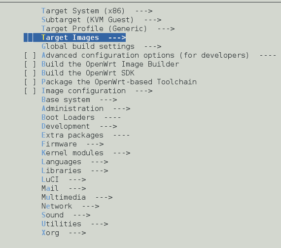
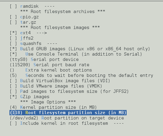
Fresh configuration: traditional way: # make menuconfig or the modern way: # make nconfig

Note: To detect memory leaks in the kernel modules, you can use the tool ‘kmemleak’. To use it, you need to compile the kernel with ‘CONFIG_DEBUG_KMEMLEAK’ option enabled. Enable it as following: make menuconfig –> ‘kernel Hacking’ –> ‘Memory Debugging’ –> ‘Kernel Memory Leak Detector’. Enable this option and do save. You can check this file “/sys/kernel/debug/kmemleak” while testing.

You can use the config file of the current running kernel. In Fedora this file exists as /boot/config-$(KernelName). For example: /boot/config-3.19.5-100.fc20.x86_64. Then update it with ‘make menuconfig’ and save.

Compilation:

Prepare for the compilation: # make mrproper

Compile the kernel: # make

Install the compiled modules:

# make modules_install

The modules will be installed in /lib/modules/3.19.5/

Install the kernel: Now we want to copy and rename the image bzImage (arch/x86_64/boot/bzImage) to /boot + creating the initial RAM disk + creating the map/kernel symbols , and update the grub config file). This done by: # make install

After compiling and installing the kernel, we can boot from it (appear in the GRUB startup List).

Header Files needed to compile a new module:

If you want to build your own kernel module, you need to have the header files.  Check the folder /lib/modules/3.19.5/build/ where 3.19.5 is the new kernel version.

The module is header and source files with Makefile file. When it is built we got .ko file. In the Makefile you need to specify the kernel source and the obj-m.

After building the module, it will be ready to be installed. You need to boot from the new kernel and do ‘modprob $ModuleName’

Again this article is just an introduction to this series. More information is coming next.


Securing the Association of the DTLS Certificate With the User’s SIP-URI

.

imagesThe SIP protocol can be used to establish SRTP security using DTLS protocol. The DTLS extension ([RFC 5764]) is used. It describes a mechanism to transport a fingerprint attribute in SDP. So the fingerprint of the self-signed certificate can be inserted by the user agent (UA) in the SDP and sent over SIP to the proxy over an integrity protected channel (carried over TLS transport protocol). The fingerprint in the SDP looks like this:

a=fingerprint:sha-1 99:41:49:83:4a:97:0e:1f:ef:6d:f7:c9:c7:70:9d:1f:66:79:a8:07

Then after the user has been authenticated, the proxy generates a hash where the certificate’s fingerprint and SIP user ID are among others included in the calculation. The proxy signs the hash using its private key and inserts the signature in a new header field in the SIP message (the Identity header field). This secure the association between the DTLS certificate and the user’s SIP URI. The Identity-Info header field helps the verifier (the receiver of the SIP/SDP message) in the verification of the signature included in the Identity header field.

The certificates are being used as a carriers for the public keys and used to authenticate the counterpart and negotiate the session keys (symmetric keys). Then the session keys are used by SRTP to encrypt/decrypt the media. The offerer sends its fingerprint in the request and the answerer sends its fingerprint in the corresponding response after accepting the offer.

Using SIP Identity and Identity-Info

The solution as i mentioned above is using the SIP Identity ([RFC 4474]) to sign the binding of the fingerprint to the user. This is done by the proxy responsible for that user. The proxy is the holder of the private key of its domain. After the user is successfully authenticated, it is authorized to claim the identity (AOR of the user). The proxy creates the signature of the hash using its private key and inserts it in Identity header field. The proxy also inserts the place where the verifier can acquire the proxy’s certificate (public key) using the Identity-Info header field.

Example:

Identity: CyI4+nAkHrH3ntmaxgr01TMxTmtjP7MASwliNRdupRI1vpkXRvZXx1ja9k
3W+v1PDsy32MaqZi0M5WfEkXxbgTnPYW0jIoK8HMyY1VT7egt0kk4XrKFC
HYWGCl0nB2sNsM9CG4hq+YJZTMaSROoMUBhikVIjnQ8ykeD6UXNOyfI=
Identity-Info: https://example.com/cert

Note the part “/cert” in the Identity-Info URL which addresses a certificate.

The Hash Generation

The signature of the hash is added as an Identity header field in the SIP message. The calculation of the hash must contain mainly the AOR of the user and the fingerprint included in the SDP in the body of the message.  According to RFC [4474], the signature/hash is generated from certain components of SIP message, among others:

  • The AoR of the UA sending the message (or addr-spec of the From header field)
  •  The addr-spec component of the Contact header field value.
  • The whole SDP body (the fingerprint is here)
  • …….

Fingerprint Verification

Using the header Identity-Info, the user agent verifies that the fingerprint of the certificate received over the DTLS handshake matches the fingerprint received in the SDP of SIP request/response.


 References


OPUS and VP9 Bitrates

.

Current WebRTC implamentations use Opus and VP8 codecs:

.The Opus codec is audio codec developed by IETF (codec IETF working group) to be suitable for interactive audio over the internet. OPUS extended from other two audio codecs: SILK, and CELT. OPUS can adapt seamlessly to high and low bandwidth. OPUS has very low algorithmic delay (26.5 ms – 5 ms). It supports constant and variable bitrate from 6 kbit/s to 510 kbit/s.

The VP8 is video codec developed by Google. It is extended from VP7. The bitrate varies from 100 to 2000+ kbit/s depending on the size and the quality of the video. Then VP9 came to reduce the bitrate by 50% compared with VP8 with same video quality.

Note: If the hardware is able to capture high quality streams, the CPU and the bandwidth must be able to preserve this.


TURN In Few Words

.

TURN is abbreviation for Traversal Using Relays around NAT. It is a control protocol that allows the host behind a NAT to exchange packets with its peers using the relay.  It is specified in the RFC [5766]. The following are few words about this protocol:

  • TURN is part of the ICE (Interactive Connectivity Establishment) but it can be used without ICE.
  • TURN is designed to solve the communication problem when both the client and its peer are behind respective NAT where the hole punching techniques (discovering direct communication path) may fail. In other words TURN is used when a direct communication path between the client and the pair can NOT be found.
  • The public TURN server sits between the two hosts that are behind NAT and relays the packets between them.
  • TURN is client-server protocol. The client is called TURN client and the server is called TURN server.
  • The TURN client obtains (using the TURN protocol -Allocate transaction) on the TURN server what is called relayed transport address (IP address and port).
  • The client sends CreatePermissions request to the TURN server to create permissions (permissions to validate the peer-server communication).
  • The TURN server sees the messages coming from the client as it is coming from a transport address on NAT. This address is called client’s server-reflexive transport address.
  • The NAT forwards packets coming to the client’s server-reflexive transport to the client’s host transport address (private address).
  • The TURN server receives the application data from the client, make the relayed transport address as the source of the packets and relays them to the peer using UDP datagrams.
  • The peer sends the application data in UDP packets to the client’s relayed transport address on the relay server. Then the server checks the permissions and on validation it relays the data to the client.
  • A way to communicate the relayed transport address and peers addresses (server-reflexive transport addresses) is needed (out of scope of the TURN protocol).

TURN

  • In VOIP, if TURN is used with ICE, then the client puts its obtained relayed transport address as an ICE candidate (among other candidates) in the SDP carried by the rendezvous protocol like SIP. When the other peers receives the SIP request, they will know how to reach the client.
  • The TURN messages (encapsulation of the application data) contains an indication of the peer the client is communicating with so the client can use a single relayed transport address to communicate with multiple peers. This is when the the rendezvous protocol (e.g. SIP) supports forking.
  • Using TURN is expensive so when TURN is used with ICE, the ICE uses hole punching techniques first to discover the direct path. If the direct path is not found, then TURN is used.
  • Using TURN makes the communication no longer peer to peer communication.

More Information


Linux NAT Using Conntrack and IPtables

.

Doing the Network Address Translation (NAT) into Linux kernel scales the performance up. This mechanism consists of two parts:

The Connection Tracking/Conntrack Modules

It is a tracking technique of the connections. It is used to know how the packets that pass through the system are related to their connections. The connection tracking does NOT manipulate the packets and It works independently of the NAT module. The conntrack entry looks like:

udp 17 170 src=192.168.1.2 dst=192.168.1.5 sport=137 dport=1025 src=192.168.1.5 dst=192.168.1.2 sport=1025 dport=137 [ASSURED] use=1

The conntrack entry is stored into two separate tuples (one for the original direction (red) and another for the reply direction (blue)). Tuples could belong to different linked lists/buckets in conntrack hash table. The connection tracking modules is responsible for creating and removing the tuples.

Note: The tracking of the connections is ALSO used by iptables to do packet matching based on the connection state.

The NAT Modules

The NAT modules do the NATing itself. They use the tuples and modify them based on the NATing rules. In this way the tuples in the connection tracking table remains in consistent state.

nat

If the packet belongs to an existing connection, this means there is already a conntrack entry (two tuples) in the conntrack table. The NAT module knows this by checking a field in the tuple created for the new arrived packet. Then the packet manipulation is done based on the conntrack entry (The manipulation is determined previously).

If the received packet represents a start of a new connection (first packet), the NAT module looks for a rule in the “NAT” table. If a rule is found, the NAT manipulation will be applied based on the rule and the tuples in the conntrack table will be changed. The tuples are created by conntrack at local outtput hook point before NAT for SNAT (Source NAT) so they need to be updated after doing the NAT for the first packet.

Assume the packets are leaving on network interface “eth1″(-o means “output”) to the internet and the interface “eth0” is connected to the local network. To change the source addresses to 1.2.3.4  and the ports 1-1023, you can add this rule:

# iptables -t nat -A POSTROUTING -p tcp -o eth1 -j SNAT –to 1.2.3.4:1-1023

You can specify a range of IP addresses as well (SNAT –to 1.2.3.4-1.2.3.6).

You can also use what is called MASQUERADE where the the sender’s address is replaced by the router’s address.

# iptables -t nat -A POSTROUTING -o eth1 -j MASQUERADE

Note: Here i am doing SNAT (Source NAT). You can also do Destination NAT (DNAT) where the conntrack hooks into pre routing hook point. To write DNAT rules, use the chain  PREROUTING and the target DNAT.

NAT Settings

  • You need to load the “nf_conntrack”: # modprobe nf_conntrack
  • You need to start iptables service: # systemctl start iptables
  • You need to enable IP_Forwarding:
    • Temporarily: # echo “1” > /proc/sys/net/ipv4/ip_forward
    • Permanently:  Write net.ipv4.ip_forward = 1 in the file “/etc/sysctl.conf ” and reload (# sysctl -p).
  • Then set NATing rules as mentioned above.
  • Add Forwarding rules to forward packets from one interface to another in both direction:

From the public (interface:eth1) to private(interface eth0):

# iptables -A FORWARD -i eth1 -o eth0 -m state –state RELATED,ESTABLISHED -j ACCEPT

From private(eth0) to public(eth1):

# iptables -A FORWARD -i eth0 -o eth1 -j ACCEPT

  • Finally you need to save the IPtables rules to be persistent: # iptables-save

Note

  • If you got this error “nf_conntrack: table full, dropping packet“ and you have enough free memory , you can expand the size of conntrack table, click here.

More Information